Liquefied Natural Gas: production process and cold energy recovery
Liquefied natural gas (LNG) is natural gas that has been cooled to about -160 °C and turned into a liquid to facilitate transportation and storage. A typical LNG supply chain consists of gas production, liquefaction, shipping, regasification, and delivery. LNG regasification releases a significant amount of cold energy that can be reused in a variety of processes, such as power generation.
What is LNG ?
The use of natural gas has grown rapidly over the past decade. According to the IEA, natural gas accounted for about a quarter (24%) of global electricity generation in 2020. Compared with other fossil fuels such as coal, natural gas emits much less CO2 and air pollutants. [1] Liquefied natural gas (LNG) is produced by cooling natural gas under pressure under conditions such that flashing to slightly above atmospheric pressure generates a cryogenic liquid boiling at <-160°C. Liquefaction facilitates the transportation and storage of natural gas, as it reduces the volume: 1 litre of LNG is approximately equivalent to 600 litres of natural gas at ambient conditions. [2–4]
Properties of LNG
Thermodynamic properties of LNG
Natural gas, from which LNG is produced, is a mixture of different gases: primarily methane (about 80-99 mole%) and the remaining components are ethane, propane and other heavier hydrocarbons, as well as nitrogen and carbon dioxide in varying proportions depending on the geographic source. [2] Equations of state are used to accurately model the phase behaviour and thermodynamic properties of LNG mixtures. [5] With increasing trade volume and growing demands to optimise energy-intensive LNG production, accurate calculation of liquid phase properties is a challenge for the industry. [6]
Environmental properties of LNG
Natural gas is often considered a transition fuel in the move toward a low greenhouse gas (GHG) economy as it is the cleanest fossil fuel, emitting 30-45% less CO2 per unit of energy than oil and coal. [7] According to an industry white paper, the use of LNG as a marine fuel can reduce GHG emissions by up to 21% compared with current oil-based fuels. [8] LNG is an intermediate technology between conventional fuels (e.g. gasoline, diesel, LPG) and low-emission fuels such as liquid hydrogen or ammonia. [3] Indeed, with LNG as a fuel, there is still a risk of fugitive methane emissions due to leakages and slips from unburned methane e.g., in engines. Methane is a greenhouse gas that contributes strongly to global warming. In response to commercial and regulatory pressures, engine manufacturers are investing in R&D to reduce methane slips. [9]
Safety issues concerning LNG
LNG is non-toxic, non-corrosive, colourless, and odourless. Nevertheless, as it is a cryogenic fluid, frost burn occurs if LNG comes into contact with human skin. LNG is usually not explosive in its liquid state. Once it is heated and becomes a gas, the risk of explosion increases if an air/gas mixture is ignited in a confined environment. In an open (unconfined) environment, natural gas does not detonate because it is rapidly diluted in the atmosphere. [10] However, the LNG vapour is highly flammable with air, which may cause flash fire. [2,4] Risks and safety measures in the LNG industry are addressed in standards, such as EN 1473:2021 and NFPA 59A. [11,12]
Typical LNG supply chain
LNG production and processing
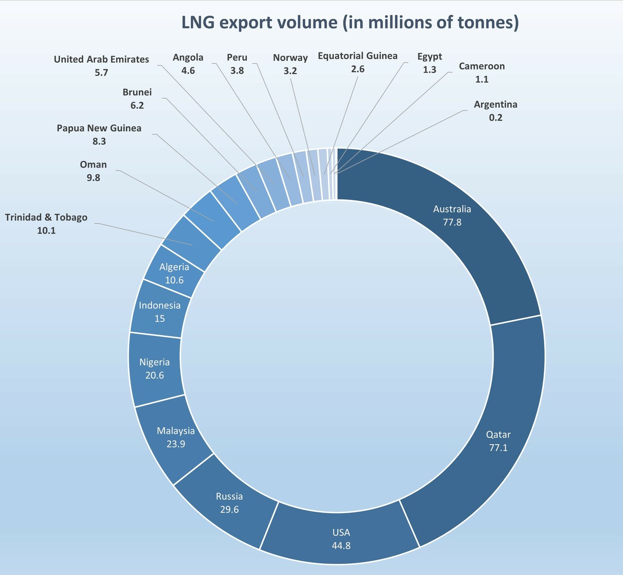
As of February 2021, 21 markets had operational LNG export facilities, according to the International Gas Union (IGU). The top two LNG exporters in 2020 were Australia (77.8 MT) and Qatar (77.1 MT), followed by the US (44.8 MT) and Russia (29.6 MT). [13]
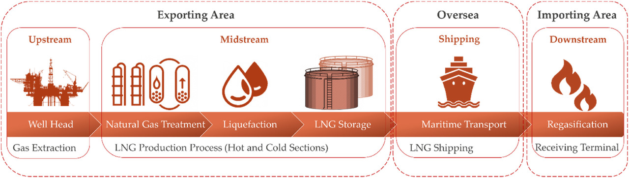
A typical LNG supply chain is composed of gas production, liquefaction, shipping, regasification, and pipeline delivery. LNG is transported cryogenically by truck, train, or ship. One liquefaction plant can serve several regasification plants and vice versa. Small-scale and offshore LNG facilities allow for the exploitation of small, remote gas resources, for which it is not economical to build a pipeline. Onshore pipelines longer than 5,000 km and offshore pipelines longer than 1,500 km are not economical compared to LNG. Energy consumption and GHG emissions are equal for onshore pipelines and LNG with transport distances of 13,000 km and 7,500 km, respectively. [7]
Natural gas liquefaction processes for onshore and offshore plants
Liquefaction plants can be divided into three categories: large-scale onshore plants (capacity > 1 million tonnes LNG per annum (MTPA)), small-scale onshore plants (capacity < 1 MTPA), and offshore processes. [7] According to the IGU, global liquefaction capacity was 452.9 MTPA at the end of 2020. The top three LNG exporting markets currently account for more than half of global liquefaction capacity. [13]
The liquefaction of natural gas is achieved through several refrigeration cycles which can be classified into three groups: cascade liquefaction processes (using pure components as refrigerants), mixed refrigerant processes and gas expansion-based processes. Gas expansion-based processes are typically used for small-scale, peak-shaving and floating LNG (FLNG) applications. [14] It has been estimated that liquefaction consumes about 30-35% of the total energy required for the LNG value chain. The energy requirement for LNG production depends not only on the liquefaction technology, but also on the site conditions. Furthermore, all process parameters must be carefully optimised. [15]
Cascade liquefaction process
The classical cascade process normally involves three refrigeration cycles, each in a different temperature range and containing pure propane, ethylene, and methane as refrigerants respectively. According to several review articles, cascade technologies are mostly used for large-scale onshore applications. [7] As of 2020, the ConocoPhillips Optimized Cascade (CPOC) process is the second leading liquefaction technology with 22% (100.3 MTPA) of operational capacity globally, according to the IGU. [13]
Mixed refrigerant liquefaction process
In mixed refrigerant (MR) processes, there is at least one refrigeration cycle that involves the continuous cooling of a natural gas stream using a blend of refrigerants (usually a mixture of light hydrocarbons and nitrogen). Variations of the MR technology include single-mixed refrigerant (SMR) and dual-mixed refrigerant (DMR) cycles. The SMR process involves a reverse Rankine cycle for chilling and liquefying the natural gas. The DMR process liquefies the feed gas using two independent MR cycles. In the first cycle, the natural gas is precooled by a heavier mixed refrigerant. Subsequently, the cooled natural gas is condensed and subcooled in a second step by a lighter mixed refrigerant. [16]
The propane precooled mixed refrigerant process (AP-C3MR) dominates the large-scale LNG industry, occupying close to 53% of global operational capacity as of 2020. [7,13]
Gas expansion-based liquefaction process
The turbo-expander refrigeration cycle in gas expansion-based (EXP) liquefaction processes works by compressing and expanding a gas to generate refrigeration. [16] The refrigerants used in the EXP process (pure nitrogen, methane, or mixtures thereof) can reach the low temperatures needed for the liquefaction of natural gas in a single loop, but at the cost of a lower efficiency than Cascade and MR processes. To reduce energy consumption, the EXP process recovers part of the compressor work by replacing the throttling valve with an expander. EXP processes are receiving increasing attention for small-scale applications. [7] Indeed, due to safety reasons and space limitations, offshore applications such as small FLNGs mostly use relatively simple liquefaction technologies. [13]
LNG shipping
In 2020, the global LNG carrier fleet consisted of 572 active vessels, including 37 floating storage and regasification units (FSRUs) and four floating storage units (FSUs). [13]
In international trade, LNG is transported in double-hulled ships, specifically designed to handle the low temperature of LNG, to a receiving terminal where it is stored and regasified. [4] LNG containment systems for LNG carriers can be split into two categories: membrane systems (79% of the current fleet) and self-supporting systems (21% of the current fleet). Most modern new builds have adopted the membrane type, which offers a thinner and lighter containment system, better fuel and space efficiency. In both systems, a small amount of LNG is converted into gas during a voyage. This is referred to as boil-off gas. Boil-off rates in recently built LNG carriers are below 0.10% of the total volume per day (around 0.15% of the total volume per day in older vessels). [13]
LNG Regasification and distribution
According to the IGU, the main importers of LNG in 2020 were Japan (74.43 MT), China (68.91 MT) and South Korea (40.81 MT), which together imported 51% of the current global LNG production. As of February 2021, 39 markets were equipped with LNG import terminals, reaching a global regasification capacity of 850.1 MTPA. [13]
At the import terminal, LNG is heated up to ambient temperature, delivering pressurised natural gas. This is accomplished using special heat exchangers fed with high-pressure pumps for achieving the final gas pressure. [4] Most regasification terminals use open rack vaporizers (ORV) to regasify LNG. Open rack vaporizers (ORV) are heat exchangers that utilise sea water as the heat energy source in a direct heat system to vaporise LNG. [17] Other types of vaporisers include submerged combustion vaporisers (SCV), ambient air vaporisers (AAV), shell and tube heat exchange vaporisers (STV), and intermediate fluid vaporisers (IFV). [5]
Offshore terminals receive LNG from LNG carriers, regasify it and deliver the natural gas to onshore customers via pipeline. There are two fundamental concepts for offshore LNG terminals: Gravity Based Structures (GBS), and Floating Storage and Regasification Units (FSRU). An FSRU is an LNG ship designed or modified to include a regasification facility. They are floating structures, either moored to the seabed or tethered to a jetty in a port area. [5]
Cold energy recovery from LNG processing
Conventional LNG regasification involves direct heat exchange between the LNG and sea water or other heat sources, meaning that the cold energy is wasted alongside the large mechanical power required to drive the seawater pumps. [18] The global potential for cold production from LNG has been estimated at nearly 12 GW. This "cold energy" could be reused in a variety of processes, such as power generation. [19]
LNG cold energy utilisation systems can be integrated into the LNG regasification process without modifying the systems drastically. In these systems, LNG is mainly used as the heat sink for the systems, while in some cases, LNG is used as the heat sink as well as the feed stream. The current LNG cold energy utilisation systems include power generation, air separation, traditional desalination, cryogenic carbon dioxide capture, and natural gas liquids (NGL) recovery. [20]
Cryogenic power generation
Cryogenic power generation is the most widely used application of LNG cold energy. [20] The following thermodynamic cycles have been considered for power generation from LNG cold energy: the direct expansion cycle, the organic Rankine cycle (ORC), the Brayton cycle, the absorption power cycle, the Stirling cycle, and a combination of these cycles. [19]
The ORC has been applied in a real engineering project in Japan since 1979. In an LNG terminal owned by Osaka Gas company, an ORC using propane as the working fluid has a power output of 1450 kW. [20] According to a review article on cryogenic power generation, a thermal efficiency of about 25-30% has been reported for combined transcritical Rankine cycles. Brayton cycles, which are suitable for high-temperature heat sources (i.e. from biomass combustion), allow for a thermal efficiency of about 70-80%. [19]
Cryogenic carbon dioxide capture
Carbon capture, utilisation and storage involves the capture of CO2 from industrial facilities that use either fossil fuels or biomass as fuel. According to the IEA (International Energy Agency), chemical absorption using amine-based solvents is the most mature carbon capture technology. [21,22] However, the large volumes of solvent used require significant thermal energy for regeneration. Among other processes, the physical separation of CO2 can be achieved using low temperature technologies, often referred to as cryogenic carbon capture. This technology is gaining considerable attention as cryogenic separation offers high CO2 recovery rates and purity levels. [21]
Cryogenic carbon capture (CCC) involves a physical separation process based on the differences between the boiling points and the desublimation properties of the components in the gas mixture. [21] The CCC process involves cooling the gases to the freezing or desublimation point of CO2 (-100 to -135 °C), separating and pressurising the solids, and then warming all streams to produce a CO2-depleted stream at ambient pressure and a pure (above 90%) pressurised liquid CO2 stream typically to about 150 bar, both at ambient temperature. [23]
Cryogenic carbon capture relies on phase change, thus separating the CO2 from the gas in the form of a liquid or solid. Gas-to-liquid carbon dioxide separation (or cryogenic distillation) is recommended for streams with a CO2 concentration above 50% to limit refrigeration and energy consumption. Vapour-to-solid separation has been considered a more energy-efficient solution. For instance, a study that compared the two options found that for a gas mixture with a concentration of 70% vol. CO2, the energy requirement for a conventional cryogenic distillation network was 1472 kJ/kg CO2, while that of a cryogenic packed bed was 810 kJ/kg CO2. [21]
Cold energy storage
As LNG regasification is a continuous process, the storage of LNG cold energy requires appropriate storage systems. Suitable storage systems for LNG cold energy include liquid air systems, liquid carbon dioxide systems, and phase change material (PCM) systems. In the case of cold energy storage using liquid air, the air is first pressurised to a high pressure by a compressor, and then cooled and liquefied by transferring heat to LNG in the heat exchanger. During the heat transfer process, cold energy from the LNG is transferred to the air to produce liquid air. The liquid air is stored in the cryogenic tank pending an energy demand. When the energy demand increases, the stored liquid air can be heated into the gas phase and expands in the turbine to generate electricity to supply power to the grid. [20]
Other applications for LNG cold energy
Challenges remain before the use of LNG cold energy can become widespread. Nevertheless, with the growth of the LNG market, innovative applications of LNG cold energy utilisation have been proposed. [20]
For instance, in Thailand, the receiving terminal of the PTTLNG company utilises a heat exchanger with propane as an intermediate fluid to transfer cold energy from LNG to water. Since 2018, PTTLNG has been using 32 MW of LNG cold energy in four projects within the LNG receiving terminal: (1) production of electricity via an organic Rankine cycle capacity of 5 MWh; (2) cooling of the air inlet of gas turbine generators to increase the generator efficiency; (3) replacement of refrigerant heating, ventilation and air conditioning systems within buildings; (4) development of winter plantations with precision agriculture to replace imported products. [24]
Furthermore, researchers performed a simulation to assess the potential of using the LNG cold energy from PTTLNG to replace the conventional cooling system in data centres. They found that combining a data centre with an LNG receiving terminal using an IFV would provide about 30 MW of cold energy, which is sufficient for cooling a data centre with a capacity of 3519 racks. Such an amount of cold energy could reduce the data centre’s cooling operation costs by over USD 10 million per annum, as well as CO2 emissions by 35,000 t per annum. [24]
Useful links for further information
For further information, the following documents are available for download on FRIDOC.
-
IIR Informatory Notes
CHRZ, Vaclav, 2006. Liquefied natural gas: current expansion and perspectives, 19th Informatory Note on Refrigerating Technologies. https://iifiir.org/en/fridoc/liquefied-natural-gas-current-expansion-and-perspectives-127329 -
Articles from the International Journal of Refrigeration
Higashi, K., Kondou, C., & Koyama, S. (2020). Feasibility analysis for intermediated fluid type LNG vaporizers using R32 and R410A considering fluid properties. International Journal of Refrigeration, 118, 325-335. https://iifiir.org/en/fridoc/feasibility-analysis-for-intermediated-fluid-type-lng-vaporizers-using-142694 -
Open access articles
Font-Palma, C., Cann, D., & Udemu, C. (2021). Review of Cryogenic Carbon Capture Innovations and Their Potential Applications. C, 7(3), 58. https://doi.org/10.3390/c7030058 -
Conference papers
Li, Y., & Wu, D. (2020, July). A dynamic simulation of a cryogenic power generation system on an LNG fuelled vessel based on ORC technology. In IIR Rankine Conference 2020: Advances in Cooling, Heating and Power Generation (p. 1204). https://iifiir.org/en/fridoc/a-dynamic-simulation-of-a-cryogenic-power-generation-system-on-an-lng-142712
ATIENZA-MARQUEZ A., BRUNO J. C., CORONAS A. (2020, July) An LNG-based system for the combined production of power and cooling. In IIR Rankine Conference 2020: Advances in Cooling, Heating and Power Generation (p. 1202). https://iifiir.org/en/fridoc/an-lng-based-system-for-the-combined-production-of-power-and-cooling-142711
Saeed, M. Z., Widell, K. N., Hafner, A., Nordtvedt, T. S., & Svendsen, E. S. (2020). Cryogenic cold utilization and system integration possibilities for LNG-driven fishing vessels. In 6th IIR Conference on Sustainability and the Cold Chain-Proceedings. International Institute of Refrigeration. https://iifiir.org/en/fridoc/an-lng-based-system-for-the-combined-production-of-power-and-cooling-142711
Acknowledgements
The IIR would like to thank Dr. Heinz Bauer, member of the A2 commission “Gas liquefaction and separation”, for his proofreading and his relevant remarks for the drafting of this summary document.
References
1. IEA. (2021, November). Natural Gas-Fired Power [Tracking report]. https://www.iea.org/reports/natural-gas-fired-power
2. Arefin, M. A., Nabi, M. N., Akram, M. W., Islam, M. T., & Chowdhury, M. W. (2020). A Review on Liquefied Natural Gas as Fuels for Dual Fuel Engines: Opportunities, Challenges and Responses. Energies, 13(22), 6127. https://doi.org/10.3390/en13226127
3. Banaszkiewicz, T., Chorowski, M., Gizicki, W., Jedrusyna, A., Kielar, J., Malecha, Z., Piotrowska, A., Polinski, J., Rogala, Z., Sierpowski, K., Skrzypacz, J., Stanclik, M., Tomczuk, K., & Dowżenko, P. (2020). Liquefied Natural Gas in Mobile Applications—Opportunities and Challenges. Energies, 13(21), 5673. https://doi.org/10.3390/en13215673
4. Chrz, V. (2006). Liquefied natural gas: Current expansion and perspectives, 19th Informatory Note on Refrigerating Technologies. International Institute of Refrigeration. https://iifiir.org/en/fridoc/liquefied-natural-gas-current-expansion-and-perspectives-127329
5. Mokhatab, S., Mak, J. Y., Valappil, J. V., & Wood, D. A. (Eds.). (2014). Chapter 1—LNG Fundamentals. In Handbook of Liquefied Natural Gas (pp. 1–106). Gulf Professional Publishing. https://doi.org/10.1016/B978-0-12-404585-9.00001-5
6. Thol, M., Richter, M., May, E. F., Lemmon, E. W., & Span, R. (2019). EOS-LNG: A Fundamental Equation of State for the Calculation of Thermodynamic Properties of Liquefied Natural Gases. Journal of Physical and Chemical Reference Data, 48(3), 033102. https://doi.org/10.1063/1.5093800
7. Zhang, J., Meerman, H., Benders, R., & Faaij, A. (2020). Comprehensive review of current natural gas liquefaction processes on technical and economic performance. Applied Thermal Engineering, 166, 114736. https://doi.org/10.1016/j.applthermaleng.2019.114736
8. European Biogas Association. (2020, November 23). New joint paper: ‘BioLNG makes carbon neutrality a reality for EU transport’. European Biogas Association. https://www.europeanbiogas.eu/new-joint-paper-biolng-makes-carbon-neutrality-a-reality-for-eu-transport/
9. Stamatis Fradelos. (2021, March 22). LNG as marine fuel and methane slip. SAFETY4SEA. https://safety4sea.com/cm-lng-as-marine-fuel-and-methane-slip/
10. Connaissance des Énergies. (2011, September 26). Gaz naturel: Quels dangers ? Fiches pédagogiques. https://www.connaissancedesenergies.org/fiche-pedagogique/gaz-naturel-quels-dangers
11. CENELEC. (2021, May). A European LNG infrastructure fit for the future: CEN published the new edition of EN 1473. CEN-CENELEC. https://www.cencenelec.eu/news-and-events/news/2021/eninthespotlight/2021-05-26-en-1473-lng/
12. National Fire Protection Association (NFPA). (2019). NFPA 59A: Standard for the Production, Storage, and Handling of Liquefied Natural Gas (LNG). https://www.nfpa.org/codes-and-standards/all-codes-and-standards/list-of-codes-and-standards/detail?code=59A
13. IGU. (2021). World LNG Report 2021. International Gas Union. https://www.igu.org/resources/world-lng-report-2021/
14. Mokhatab, S., & Messersmith, D. (2018, July). Liquefaction technology selection for baseload LNG plants. Hydrocarbon Processing. https://www.hydrocarbonprocessing.com/magazine/2018/july-2018/bonus-report-lng-technology/liquefaction-technology-selection-for-baseload-lng-plants
15. Majeed, K., Qyyum, M. A., Nawaz, A., Ahmad, A., Naqvi, M., He, T., & Lee, M. (2020). Shuffled Complex Evolution-Based Performance Enhancement and Analysis of Cascade Liquefaction Process for Large-Scale LNG Production. Energies, 13(10), 2511. https://doi.org/10.3390/en13102511
16. Mokhatab, S., Mak, J. Y., Valappil, J. V., & Wood, D. A. (Eds.). (2014). Chapter 3—Natural Gas Liquefaction. In Handbook of Liquefied Natural Gas (pp. 147–183). Gulf Professional Publishing. https://doi.org/10.1016/B978-0-12-404585-9.00003-9
17. Agarwal, R., Rainey, T. J., Rahman, S. M. A., Steinberg, T., Perrons, R. K., & Brown, R. J. (2017). LNG Regasification Terminals: The Role of Geography and Meteorology on Technology Choices. Energies, 10(12), 2152. https://doi.org/10.3390/en10122152
18. Khor, J. O., Dal Magro, F., Gundersen, T., Sze, J. Y., & Romagnoli, A. (2018). Recovery of cold energy from liquefied natural gas regasification: Applications beyond power cycles. Energy Conversion and Management, 174, 336–355. https://doi.org/10.1016/j.enconman.2018.08.028
19. Pospíšil, J., Charvát, P., Arsenyeva, O., Klimeš, L., Špiláček, M., & Klemeš, J. J. (2019). Energy demand of liquefaction and regasification of natural gas and the potential of LNG for operative thermal energy storage. Renewable and Sustainable Energy Reviews, 99, 1–15. https://doi.org/10.1016/j.rser.2018.09.027
20. He, T., Chong, Z. R., Zheng, J., Ju, Y., & Linga, P. (2019). LNG cold energy utilization: Prospects and challenges. Energy, 170, 557–568. https://doi.org/10.1016/j.energy.2018.12.170
21. Font-Palma, C., Cann, D., & Udemu, C. (2021). Review of Cryogenic Carbon Capture Innovations and Their Potential Applications. C, 7(3), 58. https://doi.org/10.3390/c7030058
22. IEA. (2021). About CCUS. IEA. https://www.iea.org/reports/about-ccus
23. Baxter, L., Hoeger, C., Stitt, K., Burt, S., & Baxter, A. (2021, April 5). Cryogenic Carbon CaptureTM (CCC) Status Report. 15th Greenhouse Gas Control Technologies Conference 15-18 March 2021. https://doi.org/10.2139/ssrn.3819906
24. Sermsuk, M., Sukjai, Y., Wiboonrat, M., & Kiatkittipong, K. (2021). Utilising Cold Energy from Liquefied Natural Gas (LNG) to Reduce the Electricity Cost of Data Centres. Energies, 14(19), 6269. https://doi.org/10.3390/en14196269
Search in the encyclopedia for articles on the following topics:
Cryogenics and gas processing | Refrigerants and secondary refrigerants | Refrigerating equipment | Cryobiology and cryomedicine, freeze-drying | Application of refrigeration to perishable products | Refrigerated storage | Heat pumps, energy recovery | General information on refrigeration, energy and environment